1
2
3
DPedal Build Instructions
Tools
| Tool | Required | Link | Notes |
|---|---|---|---|
| 3D printer | Optional | I personally have a Prusa mini, but these days the Bambu Lab P1S is a much better option. | |
| Soldering iron | Required | I personally have a Hakko FX-888D, but a Pinecil or similar is a better budget option. | |
| M3 Hex key or screwdriver | Required | Amazon hex-key set | |
| Helping hands | Helpful | Omnifixo | You can definitely complete this project without helping hands, but it'll make soldering easier |
| Side cutters (also called many other names) | Recommended | Amazon | For removing the joining material on a keycap/dpad bundle. |
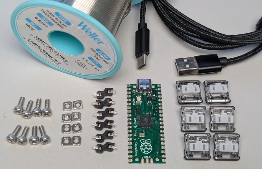
Standard Parts
| Part | Quantity | Link |
|---|---|---|
| Raspberry Pi Pico 1 USB C clone (headerless) | 1 | Amazon, AliExpress |
| 2m USB C<->A cable | 1 | Amazon |
| 8mm M3 machine screws | 8 | AliExpress |
| M3 square nuts | 8 | AliExpress |
| white choc v1 switches | 6 | AliExpress |
| choc v1 hotswap sockets | 6 | AliExpress |
| Solder | a bit | Amazon |
Note: The official micro USB version of the Pico will also work fine, but I recommend the unofficial USB C clone, since USB C is a nicer connector. Just make sure to get one that matches the dimensions of the official Pico, including the components on the pico which can be placed differently in some clones.
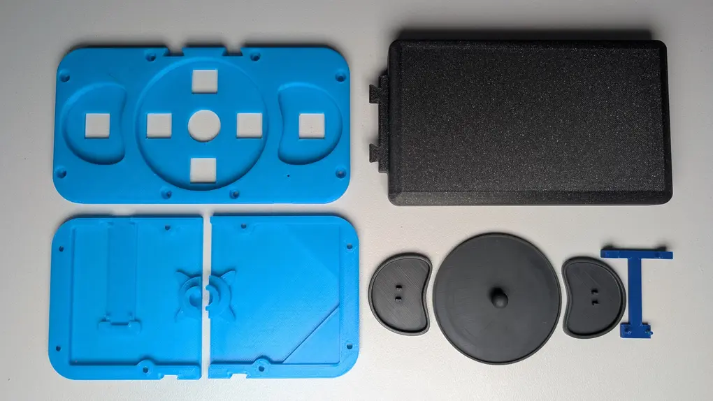
Printed Parts
First download the STLs here. Then find a way to print them.
You can choose to print these parts at home or via a printing service like JLC.
| Part | Quantity | Method |
|---|---|---|
| Footrest | 1 | Print "footrest.stl" via home FDM or order from JLC |
| Base With Pico | 1 | Print "base with pico" via home FDM or order from JLC |
| Base Without Pico | 1 | Print "base without pico" via home FDM or order from JLC |
| Switch Plate | 1 | Print "switch plate.stl" via home FDM or order from JLC |
| Soldering Jig | 1 | Print "solder jig.stl" via home FDM or order from JLC |
| Keycap | 2 | Recommended to order a resin print from JLC via the "SLA dpad-keycap bundle.stl" file, as most home FDM filaments will produce brittle pins that snap off. However, there is a separate "keycap for FDM printers.stl" file if you want to try. If ordering from JLC, the bundle is cheaper than ordering the parts individually because JLC charges more per part, but only slightly more for a larger part. |
| Dpad | 1 | Recommended to use the dpad included in the "SLA dpad-keycap bundle.stl" file. While FDM printing this part is not a problem, the DPedal looks nicer with matching keycaps and dpad. |
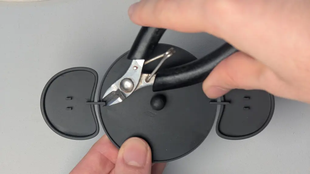
Cleanup
If you order the "SLA dpad-keycap bundle.stl" from JLC you will need to snip off the connective parts with a side cutter.
Ordering Printed Parts
- Download the STLs here, and extract them from the zip file.
- For each part to be ordered
- Go to JLC3DP
- Click "Add 3D files" and upload the STL for the part.
- Set "3D technology" + "Material"
- The following are known to be suitable for the button keycaps + dpad
- SLA(Resin) -> Black Resin
- Set "Qty" as per above table
- Set "Product Desc" to:
- "Office Appliance and Accessories" -> "Plastic Keycaps" (for keycaps + dpad)
- "Office Appliance and Accessories" -> "Plastic Keyboard Enclosure" (for everything else)
- Save to cart
- Complete the next section about ordering the PCB before completing the order. This will save on shipping cost by shipping the PCB and printed parts together.
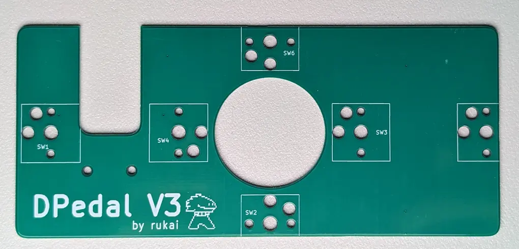
Ordering the PCB
DPedal uses a custom PCB which must be ordered from a PCB manufacturer.
- Download the dpedal_gerber_files.zip, do not extract it.
- Go to JLCPCB, click "Add gerber file" and upload the dpedal_gerber_files.zip
- Set the following options, leaving the rest as default:
- Surface finish: LeadFree HASL
- PCB thickness 1.2mm
- PCB Color: whatever you want
- Save to cart.
- Check out your order.
- You probably want "Global Standard Direct Line" for shipping.
- Make sure all printed parts in your cart are included in the order.
Printing at home
Any printed parts that you didnt order from a service will need to be printed at home.
Download the STLs here.
Then slice and print each part with the following configuration:
- default orientation with no supports
- layer height: 0.10mm (The model is very precise, so don't go any higher than this)
- infill: 15% grid infill (I just use grid because its the default, any infill type is probably fine)
- Filament: I use PLA but any hard filament should work fine.
Time Passes
Wait patiently (or impatiently) for the various orders to arrive.
Soldering
If its your first time soldering, iFixit has a nice introduction. They stress the importance of flux, and while flux is important, the soldering required for this project is simple enough you can get away with skipping it. You should also learn about iron tip maintenance.
For lead-free solder I reccommend setting your iron to 350 degrees.
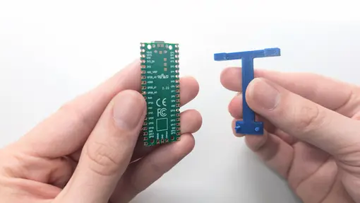
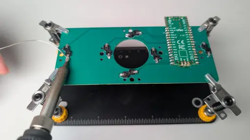
- Take the soldering jig and Pico.
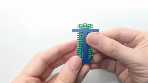
- Connect soldering jig into the Pico via the through holes and pins
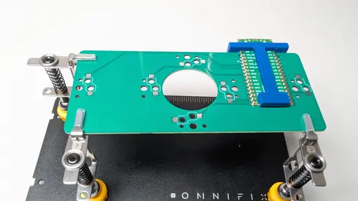
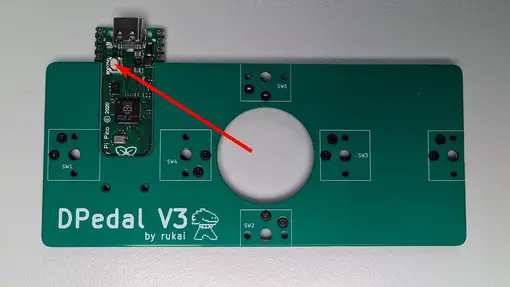
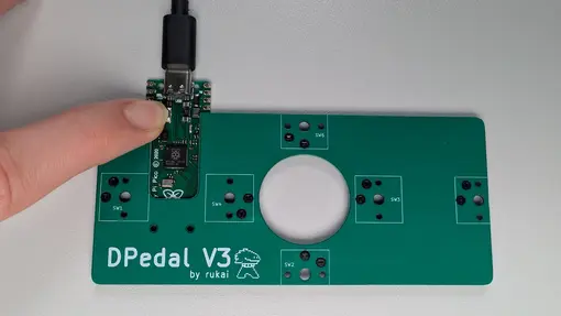
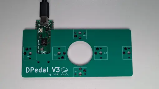
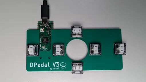
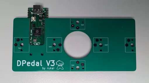
- Connect Pico to the PCB via the jig, it may need to be pushed until clicking into place. The Pico should sit secure and flatly on the PCB. Make sure the orientation matches the image.
- NOTE: If the Pico is not sitting flat against the PCB, some masking tape can be used to secure it.
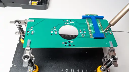
- Solder Pico to the PCB. For every pad on the PCB, heat both the pad on the Pico and the pad on the PCB with the tip of the soldering iron, while feeding solder into the point where the iron and two pads connect.
- WARNING: The solder should not form large blobs on top of the Pico or you may have trouble fitting the PCB into the case.
- NOTE: Having this many small pads close together may sound tricky with risk of shorting adjacent pads, in reality as long as you use only a minimal amount of solder, its not too bad as solder will want to stick to the hot metal surfaces and avoid the green PCB surface. However if you do manage to join some adjacent pads, you might find solder wick helpful.
- Place hotswap sockets into their holes on the PCB and solder the sockets to the PCB: Heat the ends of the socket and the pad on the PCB with the iron, while feeding solder into the point where the iron, PCB pad and socket end meet.
Flashing firmware
- Start holding down the bootsel button. Do not let go.
- Connect the Pico/PCB to your computer via USB.
- Let go of the bootsel button.
- Follow the steps below depending on your OS:
- macOS
- Download the firmware (arm host) and unzip.
- Open a terminal to the directory containing the firmware and run ./dpedalflash
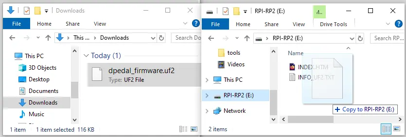
- Windows
- Download the firmware (UF2 file)
- The Pico should present itself as an extra drive. Click and drag the downloaded dpedal_firmware.uf2 onto the Pico's drive
- Linux
- Download the firmware (x86 host) and unzip.
- open a terminal to the directory containing the firmware and run ./dpedalflash
- Insert a switch into each socket
- WARNING: the orientation of the pins is different for each socket, make sure the switch is oriented correctly as you insert it.
- Open this page and test each button works, the default button mapping of the DPedal has mouse scroll on the dpad and page up/down on the left/right buttons.
- If the pedal is not working as expected, go back and examine your solder joints for cases where the joint is not sufficient for connectivity or is shorting with an adjacent joint.
- Unplug from the computer and disconnect the switches again, to prepare for the next stage.

Assembling
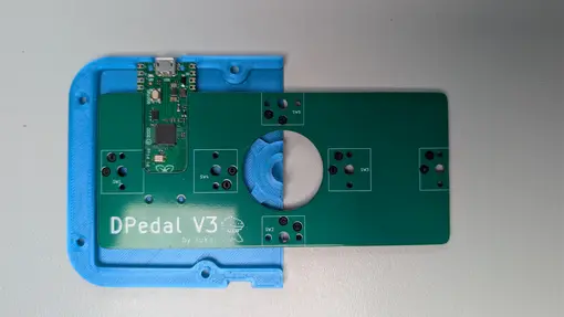
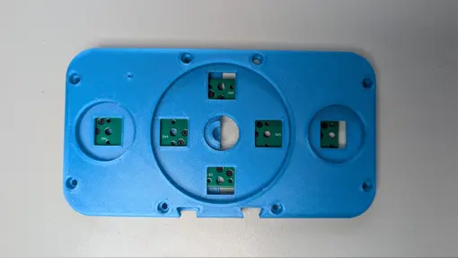
- Place PCB into the base part with the hole for the USB port.
- Place switch plate on top of the PCB
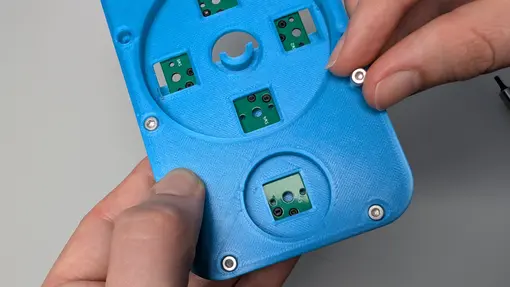
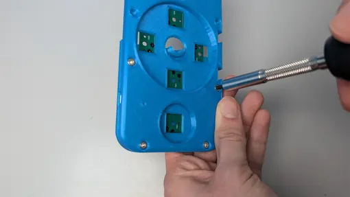
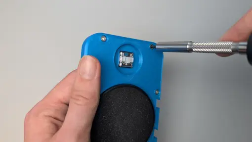
- Place 4 screws through the switch plate and base.
- For each screw, hold a square nut behind it and screw them together.
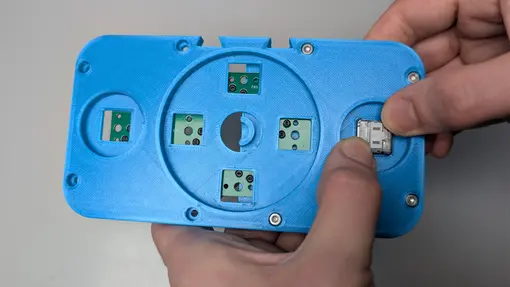
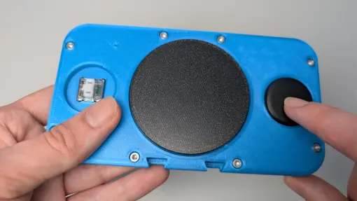
- Push all 6 switches into their sockets until they click into place.
- WARNING: the orientation of the pins is different for each socket, make sure the switch is oriented correctly as you insert it.
- Put the dpad between the two base pieces and push the pieces together.
- Screw the remaining base part to the switch plate, using 4 screws and 4 nuts.
- Push the 2 buttons into the 2 empty switches
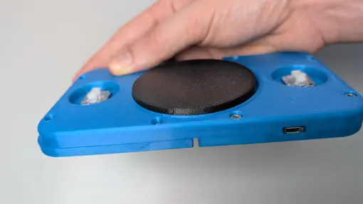
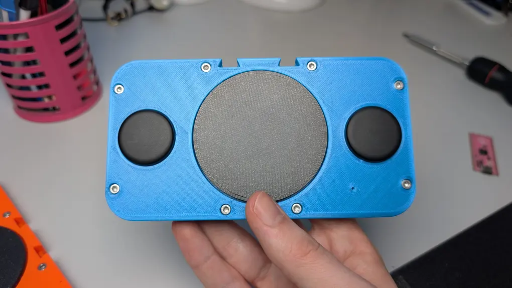
Finished!
Your DPedal is now fully assembled and ready to use.
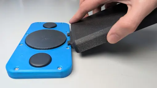
Slot in the footrest when using it.
If you want to change the keyboard/mouse mapping you can use the web configurator.
Community
Something not working out? Or want to share the results of a successful build?
Join the Discord!